- Call Us : 044 - 4301 6191
- Email us : marketing@shreevenus.com
Overview
In a HVAC system, the potential noise sources are AHU, terminal units and room air outlets. The sound wave generated by these sources transfer its energy throughout the duct and to the occupant’s area as shown here
Basics of Sound
Sound Power and Sound Pressure are different in that Sound Power is a measure of total energy per unit time emitted by the source in all directions. Sound pressure is a measure of pressure variation at the receivers location.
Sound Pressure is dependent on the acoustic environment. The factors involved include the effects of nearby reflecting surfaces, receiver distance, type of space, the amount of location in the space, the presence of barriers, and the intrusion of ambient sounds. Therefore, the sound pressure resulting from a given AHU – generated sound power depends on:
Distance from the AHU to the room
The size of the room
The absorptive properties of interior furnishings
Attenuating elements such as silencers, duct liner, duct branches, elbows , etc
Sound Wave
Insertion loss is the decrease in sound pressure levels that can be expected when a silencer is inserted into the path between the source and the receiver.
Pressure Drop is the difference in static pressure from the inlet to the outlet.
Regenerated Noise is the sound power created when airflows through a silencer at a given velocity and direction (forward or reverse).
Noise Criteria (NC) is a single number rating derived from sound pressure levels in all eight octave bands, and is intended to predict an occupant’s response to the overall sound level. The critical octave bands for evaluating sound performance ranges from 63 to 8000 Hz. To determine C rating value, sound pressure levels are plotted with a family of criterion curves shown in Figure. The level which intersects the highest curves determines the overall NC rating.
Calculating an NC Value
The NC rating can be obtained by plotting the octave band levels for a given noise spectrum against the NC curves. In this example , the following 1:1 octave bands have been measured:
| Frequency Hz | 63 | 125 | 250 | 500 | 1000 | 2000 | 4000 | 800 |
|---|---|---|---|---|---|---|---|---|
| Octave Band Level dB | 74.1 | 75.3 | 68.9 | 59.6 | 49.3 | 42.9 | 41.0 | 41.0 |
These values can be compared to those in the NC data table and a value obtained for each octave band . The NC value is the lowest NC curve which is not exceeded by each individual frequency band.
| Frequency Hz | 63 | 125 | 250 | 500 | 1000 | 2000 | 4000 | 800 |
|---|---|---|---|---|---|---|---|---|
| Octave Band Level dB | 74.1 | 75.3 | 68.9 | 59.6 | 49.3 | 42.9 | 41.0 | 41.0 |
| NC Value | NC 55 | NC65 | NC65 | NC60 | NC50 | NC45 | NC45 | NC40 |
The highest of these is the 125Hz band with an NC value of 65 and therefore the overall NC for this measurement is NC 65
Indoor Design Goals for Air Conditioning Sound Control (As Per ASHRAE 2001, Fundamentals, Chapter 7, Table 11.)
| Type of Area | Recommended NC Criteria Range |
|---|---|
| Private Residences | 25-30 |
| Hotel Meeting Rooms | 25-30 |
| Office Conference Rooms | 25-30 |
| Office Computer Equipment Rooms | 40-45 |
| Hospital Wards | 30-35 |
| Hospital Operating Rooms | 35-40 |
| Mosque | 25-30 |
| School Lecture And Class Rooms | 25-30 |
| Libraries | 35-40 |
| Concert Halls | 30-35 |
| Legitimate Theatres | 30-35 |
| Recording Studios | 30-35 |
| Movie Theatres | 30-35 |
| Laboratories With Fume Hoods | Laboratories With Fume Hoods |
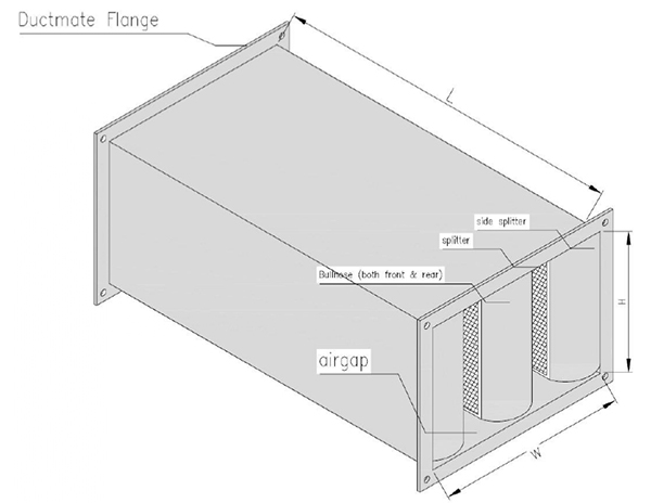
Sound Attenuator Construction
Casing: High quality galvanized steel sheet of 1 mm thickness (standard); up to 1.2mm for bigger sizes.
Splitters/Baffles: “Bull-Nose” / Centre Splitter (Pod) construction using high quality perforated galvanized steel sheet of 0.7mm thickness.
Acoustic Media: Inorganic ,fire resistant , vermin and moisture proof sound absorbent glass wool of 64kg/m³ or 50kg/m³density.
Rectangular Attenuator
Product Order Checklist:
Required room sound criteria.
Airflow data for each silencer
Duct size and maximum length available for silencer to fit in.
Details of the air-handling units with its noise levels.
CAD drawings with clear details of duct routing from each unit and duct- size till the first air outlet.
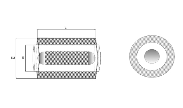
Circular Attenuator
Options Available Upon Request (Non Standard):
Flange : M.S angle frame
Flange width : 30mm or 40mm
Media : Fiber glass woven glass fabric as line
Air gap: From 50mm – 250mm to suit product requirement
Casing Material: Stainless steel or Aluminium.
Software Selection
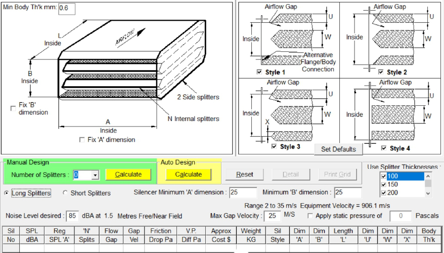
The first step in selecting a suitable attenuator configuration is to choose a model that meets the required insertion loss. This will determine the length and module width of attenuator.
The next step is to determine the width and height of the attenuator. The height can be selected to suit the application.
Thirdly calculate the pressure loss and regenerated noise. The air flow through the attenuator is required for both calculations. If the pressure loss and/or regenerated noise are too high then the width and/or height of the attenuator need to be increased.
Calibration of the Attenuators
The use of Calibration is to verify whether the selection of the attenuator made by the software is accurate.
Here we have Noise Generator, which generates noises of different frequencies as required by the user.
After which we place the sound attenuator.
And at the outlet of the sound attenuator we place the real time analyzer which shows the dB level of the source noise after it attenuated by the sound attenuated, from which we could infer whether the selection made using the software is correct.